This weekends engine rebuild

After what must have been the longest Devon to Leicestershire trip I can remember doing, I arrived on Friday night with a view to getting the bottom end of the Scott Super Squirrel racer rebuilt by Sunday afternoon.

I knew that I was going to change the main bearings, as the ones I had were a bit notchy in the case. I also wanted to do some more gas flowing on the crankcase to allow me to use another inlet port that was blanked off by part of the crankcase as my calculations had shown that I was deficient in the inlet gas flow. I also wanted to check the static flywheel balance and the crank assembly end float and alignment.

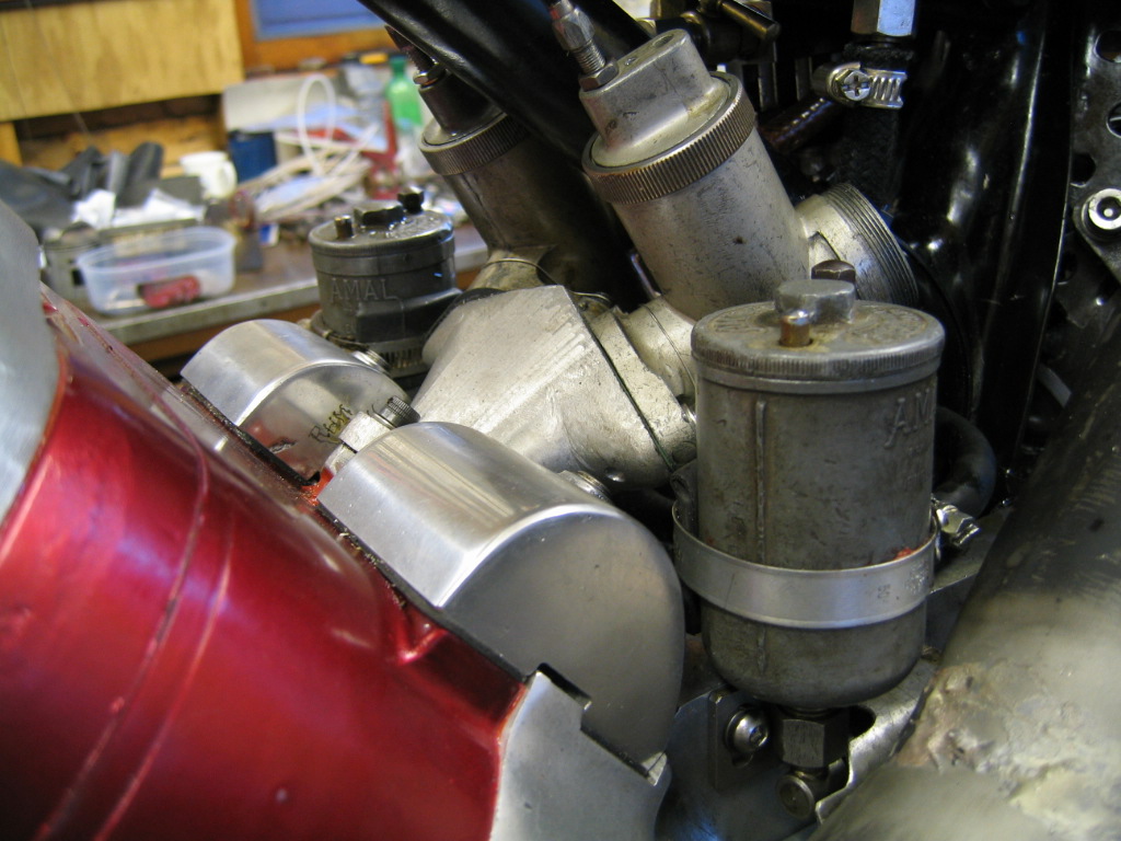
The first thing I did was my porting as I knew I’d have to clean up the cases before replacing the main bearings.

Opening up the last inlet port.
It’s all so much easier with proper air tools! I’ve been spending hours with a riffler file to do stuff I could do with an air tool in less than half the time. Files are safer though! Easy to make a mistake with an air grinder.

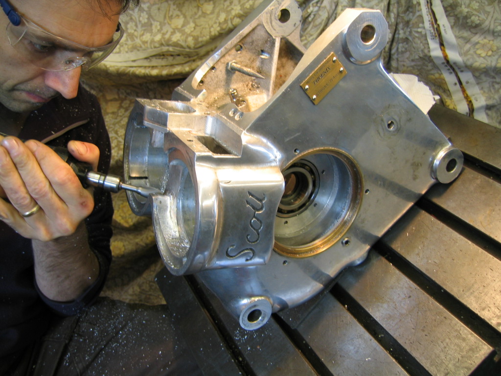
Apart from a little de-burring here it is finished:

Just finished grinding the final inlet port access.
Scott cases ready and waiting for attention at Mossengineering
Roger working on a customers engine.

One of the first things we noticed when we looked carefully at the crankshaft assembly was there looked like there had been some movement on a crank taper. Wanting to err on the side of caution we set up a lap on his Thiel 158 jig borer to just make sure that the tapers were good and clean in the flywheel. A bit of gentle lapping and all was fine.

Lap for cleaning up minor surface damage in tapers.

Next, we checked the static flywheel balance before ‘knocking up’ the crankshaft/flywheel assembly for checking the distance between inner control faces on cranks. This, we compare to the bearing face to bearing face measurement of the crankcase to determine the end float as you cannot feel and measure it by simply moving the crank side to side when installed as I used ball races and not rollers as standard.

Static flywheel balance
Drilling flywheel for balancing

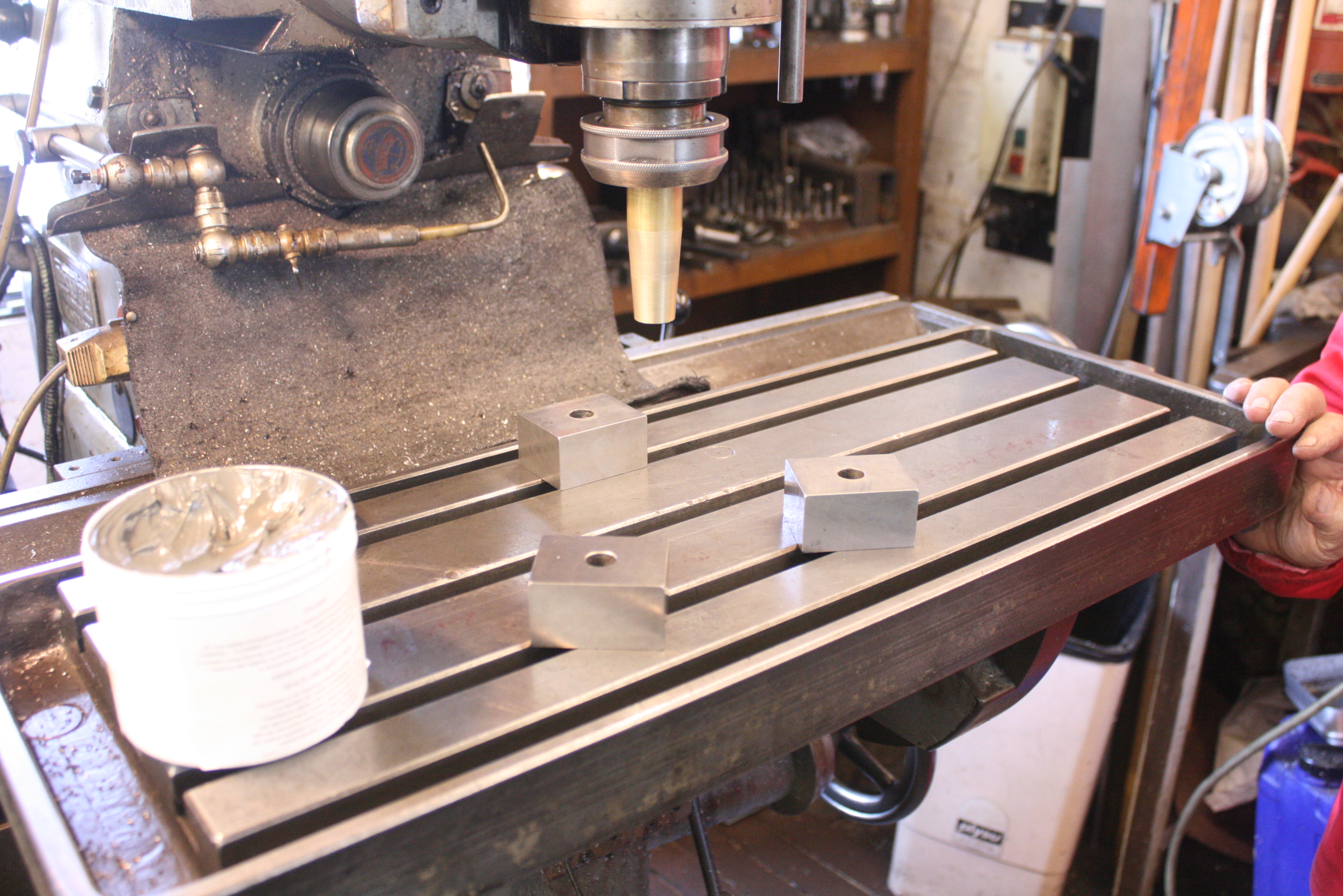
See here Roger’s magnificent Thiel 162 horizontal jig mill. We dug out the floor with a mini digger and filled it with at least 1 meter deep of concrete to create a sturdy foundation for this. Table rotates 360° and flips up to 90°, whilst the whole machining column can move in and out. The spindle then can be moved forward/back and up/down.

Thiel 162 Jig mill
Thiel 162 Jig mill

Tooling
Tooling

The Smart and Brown 1024 VSL lathe is a good place to put up the crank and flywheel assembly between centres (he sells these if anyone’s interested) IMG_4182We measure skip and run-out just to make sure there are no problems.
Checking the crank assembly for run-out

I made a new key, using slip gauges to determine the width. You have to be careful to check the height of the key as well as the length in case these prevent the flywheel tapers from safely locating in the flywheel.

Flywheel/ crank timing key. This is to time only and is not for driving purposes.

After all this, and before the assembly, the old bearing were removed and the cases heated to accept the new ones. The 22 tooth drive sprocket was deemed to be too worn and a replacement was bored out to suit the spigot and fitted.

measuring for the new drive sprocket

After that the new oil seals were fitted to the housing behind the main bearings and then the cranks finally installed and ‘knocked up’. The key doesn’t transmit load, it absolutely is not meant to… the taper has to do that. The crank tapers are driven in by tightening the centre bolt and then (with adequate provision to provide a dead stop on the other side) the centre of each crank is struck using an aluminium mallet, or large diameter drift alternately whilst continuing to tighten the centre bolt. There will come a point where the bolt cannot any longer be easily tightened and this is then considered done.

All in a very successful couple of days and a bottom end that should hopefully last for a while!

Scott Super Squirrel tuning continued- port calculations

It’s been a dispersed couple of weeks on the Scott front but I have been making progress. I’ve been reading the Jennings book on two stroke tuning from the early seventies. It’s quite well respected and has some fairly straightforward explanations of what modifications are likely to do what. The Scott is a bit unusual though and its extraordinary torque at low revs is something I would like to keep.
Let me say that everything from this point on is me trying to work something out, rather than prescribing a best practice!

It’s difficult to know who to listen to but I’ve used Jennings’ recommendations to establish the important points about the inlet, exhaust and transfer ports, those being the time that they are open and the area that is available for gas flow.
He doesn’t use the entire area, but actually has a method for calculating a mean area which is significantly smaller, but apparently more representative.
His assertion is that regardless of the size of a cylinder it will need a certain time/area to achieve optimum power at any given speed of crank rotation and I’ve created a spreadsheet to assist in calculating what’s happening. Doing the maths, combined with looking at the port timings of other engines, have given me some indications of where to go.

Ok.
This is a useful chart that was once published in Yowl:

Timing info

From having seen many Scott iron block castings, I can say that the port cores were seldom perfectly aligned. Certainly on my detachable head block the port apertures are at angles to each other and vertically misaligned slightly also between the two cylinders. The difference between cylinder timing durations is not insignificant: 4° on the transfer, 3.5° on the exhaust but only 1° on the inlet.

My own as yet standard timings (from one cylinder) started off as follows:

Exhaust: 159.5°
Inlet: 129°
Transfer: 134°

With those timings, I calculated using Jennings method that the combination of available exhaust port area and it’s time open would provide optimum power at 3500rpm, the transfer at 3250rpm and the inlet at about 3100rpm. Of these, the transfer and the exhaust figures are exactly standard, where-as the inlet differs for a couple of reasons.

1: As we have ported pistons to aid the gas flow from the crank chamber on the transfer phase, the rear part of the inlet gallery is blocked up on my engine (otherwise the port in the piston would communicate with the inlet gallery). This means that I have less actual inlet area available than standard. However, since the standard inlet gallery ports are quite small and each bridged, mine has the bridge removed between two and the port raised (as far as possible) to enable more area. My guess would be, that simply adding up the area without taking into account the effects of turbulence around the bridges at higher gas speeds is ignoring an important factor. Whether the gas speed ever gets high enough (given the amount of ports in the gallery) in a standard engine for this to be a truly limiting factor, I don’t know.
2: Our inlet timing is already extended from standard by the removal of about an 1/8″ skirt at the bottom of the piston. According to the tables available, this amounts to a difference of about 17° in total duration over the standard figure.

The standard port timings are really set up for a low engine speed, and the power and torque curves shown on dyno charts bear this out. Here are some charts to see this:

original Scott dyno test sheet

My Super squirrel racer, running methanol, tested on a dynojet rolling road dyno (albeit with RH blown head gasket) in October 2013.

Super Squirrel racer HP Dyno chart (Oct 13)
Super Squirrel racer torque curve (Oct 13)

Although the fact that the head gasket was blown means that the results themselves are not reliable, the curves are likely to be, and so I can at least see where (with the expansion chamber fitted) the torque and power is being made.

So you can see that the torque curve gives a good spread of consistent peak torque between 3200rpm and 4200rpm. You can also see that everything stops at 5000rpm, although I’m not sure I understand exactly what that shows. I’m assuming it is showing that the output drops off sharply and not just that the bike was only revved to 5000rpm during the test as you expect the curve to just terminate high if that were the case. This tailing off is definitely something to look at.

This torque curve does show that the output roughly corresponds with the Jennings based predictions. The expansion chamber will alter the results according to it’s own harmonics too, and in a perfect world I’d have run a straight pipe to try to remove that effect… but I only had an hour that time. I may do this in the future.

So, I should have a look at how this curve works within my gear ratios. It’s all a bit more important when you’ve only got three. I know it works really well at the moment, so I’m simply hoping that by not trying to do anything too extreme I shouldn’t have any problems.

I have set up the spreadsheet to show the % percentage of the optimum time area figure I am achieving for any given revs. This enables me to change a port duration figure, or a port width and instantly see its effect as a % of the optimum. Theoretically.
Alongside this, I also have some figures from A.Graham Bells book on two stroke tuning from the eighties which gave details of conclusions drawn from the known port timings for different engine configurations. By extrapolating the results to 5000 rpm, it seems 140° would be in sequence for the inlet, the exhaust would be around 165° and the transfer would seem to already be long at 134°.

So, how so these look on the Jennings spreadsheet?

As things are at the moment, the optimum theoretical rev/minute figure corresponding to my port timings (regardless of exhaust influence) is between 3100rpm and 3500rpm. With the above inlet port duration modification plus a little widening of ports, the figures say that I’ll be able to create the optimum time/area conditions for power at 4000rpm. That would be, around 135° for the inlet, 160°° for the exhaust and to leave the transfer alone.

I’ve got this week to finish the ports, I’ve ordered some new main bearings and next weekend I’ll be rebuilding the engine.

Roger’s Flying Squirrel racer – some pictures

Whilst I work out the port timing calcs, here’s a very early picture of Roger’s Flying Squirrel racer frame to illustrate his description in the comments to the post ‘The evolution of the Super Squirrel racer’

Top triangle was a design to remove the role of the standard frame's lower rails to retain rigidity.
Top triangle was a design to remove the role of the standard frame’s lower rails to retain rigidity.

The crankcase in this shot is, I believe the last standard Scott case that he ever used but fitted with the four bearing crank he made to help stem the tide of standard longstroke overhung crank induced engine carnage. Note the odd shape of the doors with the bolts in the middle. These are just blanking bolts; once removed a slide hammer can be attached to the doors to extract them as they obviously have to be a good fit to support the crank assembly.
The strength of the crank assembly was proven in quite extreme circumstances when there he started it at a meeting and it fired on one before hydraulic locking on the other cylinder, in which there had been a water leak. The contest of strengths was lost by the crankcase, which split across the main bearings. So much for sorting the crank problem.
Another interesting thing to note is the blind head block, which I believe was aluminium. This didn’t have any kind of higher compression inducing form work in the top to match the pistons, as his detachable heads do, but it would have been lighter than standard and running Silk pistons as we still do now.
just found some photos of the whole assembly:
Aluminium block and EN24T four bearing crank assembly. That's a titanium rod as well, in about 1977!
Aluminium block and EN24T four bearing crank assembly. That’s a titanium rod as well, in about 1977!

Also here’s a picture of him working machining a crankcase for Ted Parkin’s Scott. I believe this has extra large doors to take a set of special extra long stroke cranks.

Thicker sections, bigger port tracts, better material and designed to take replaceable main bearings with modern oil seals.

and here is Ted’s racer with new engine in place.

OLYMPUS DIGITAL CAMERA

Super Squirrel tuning for 2014

Although I’m unlikely to be able to afford to do anything like a full season this year, I’m pushing to try and get the Super Squirrel engine rebuilt to be as competitive as possible. It’s quite heartening to know that it went as well as it did as there had been little in the way of time spent on the detail of gas flow and port timings within the engine. Sometimes you have to stand back and re-evaluate why you are doing what you are and whether the original reasons still exist. I’ve done this and have some thoughts for ways to extract more power.

As it is, the port timings have been unchanged from standard, except for the inlet which has a slightly longer duration due to having relieved the skirt by about 1/8″. I didn’t change them because I didn’t want to lose the tractability and strong torque at low revs that the engine produces. I am still running a three speed box with ‘vintage close’ ratios and it’s important to have as much flexibility in the power band as possible. So, the idea was to increase the power and efficiency without narrowing the range too much.
The power of the engine seems to have been noticeably increased(though I lack proof of this) by using this new exhaust showing, i think, that it is effectively ramming unburnt gases back into the cylinder prior to the closure of the exhaust port. This has been a success which needs building on as I still think that there’s a significant amount of further power to be had by careful development.

I thought I’d start by looking at the obvious impediments to gas flow. I’ve been using Jennings book on two stroke tuning for guidance but essentially the idea is to have a gas flow which is not full of disruptive internal turbulance. The turbulences can be caused by changes in the surface of the ports, either things sticking up or the surface falling away (bumps or hollows). Also flow out of and into ports is facilitated by radii on edges. I’m applying this to all my ports and piston ports as a beginning, though minimally on the top edges of the ports where the timing will be affected. I’ve got a pair of Roger’s ‘high flow transfer ports’ which have no internal bridge and a non symmetrical shape, the idea being to send the transfer gas into the hump on the piston rather than over it. I always intended to spend time matching them exactly to the transfer ports on the crankcase and the block and two weeks ago I decided that the time was upon us.

I started with the crankcase and worked steadily on the left transfer aperture and found that when I’d absolutely matched the aperture to the cover, I’d increased the aperture from 904mm²(1.4″²) to 994mm² (1.54″²). That’s a 10% increase in area and the removal of edges over which eddies can form in the gas to restrict flow even further.

Transfer port work. 10% bigger on left before work commenced on right.

There was a bit of work to the covers themselves in matching to the transfer port openings on the block, but no work on the block on either the top or bottom edge , though a little at the sides to prevent the gas hitting the sides of the port. This gave me fractionally less area as it entered the ports. My understanding is that this is preferable as the gas speed is increased and the tendency to have internal turbulence affecting flow is less.
Once I’d dealt with these, I looked at the transfer ports themselves.
Whilst the engine was still together I’d noticed the height of the top of the skirt at bottom dead centre and found that it was around 1/16″ below the transfer ports both sides. To my mind this gave at least some opportunity to use some of this available space and at present I have elected to radius the bottom edge of the port to assist flow and also deepen the port in the middle adjacent to the bridge by that 1/16″ as well as radius the bridge on the transfer side.

before... (note blocked up inlets)
before… (note blocked up inlets)

Afterwards.
Afterwards.
I thought that there would be gas displacement when the flow hit the bridge and deepening the port there would give it somewhere to go.

The timings themselves are:

Transfer: 134°
Inlet: 129°
Exhaust: 159.5°

I have to be cautious about messing around with the port timings too much, as Scott barrels are no longer commonly (and cheaply) available should I completely mess it up. There is, however, a factor that has never really featured in Scott tuning before, that we now have got an expansion chamber exhaust which goes some way to (over) compensate for the effects of enforced silencing to 105 db. This means that the inlet gas, which was originally intended only to be subject to a pumped transfer is also possibly assisted by the expansion chamber extracting gases through the transfer, which would leave a negative pressure in the crank chamber. If this is taking place, then there is possibly also merit in extending the inlet duration further as there is possibility that more gas could be introduced without it spitting it back out. This also might be assisted by the use of the twin carb manifold and long inlet tracts contributing some inlet inertia to the situation.

previous engine with twin carb minifold fitted
Whether in fact the 289 carbs I have for this are too big to allow the gas speed and inertia required for this (and atomisation of the methanol) I don’t know. It’s be a suck it and see. I do have a rolling road dyno down the road and the smart money would be to run the single carb and then try the twin set-up and see the difference. Unfortunately my attempt to Dyno test at the end of last year to provide me with comparison figures didn’t go to plan as the head-gasket was blown from the beginning.

I need to do some port timing calcs (time/area) and continue the flow work to the crankcase and ports.

The evolution of the Super Squirrel racer

I’m doing things backwards here. I realise that I need to give some more of the the original history of the Super squirrel and how Roger’s Flying Squirrel racer came about. As I said in the previous post, the Super Squirrel racer is really only just returning to having the potential of competitiveness that it did in the early 1970s.

Super Squirrel racer, prior to frame modifications (around 1971/2). Note Roger's Laverda SF750 production racer with race kit. An unusual racing stable.
Super Squirrel racer, prior to frame modifications (around 1971/2). Note Roger’s Laverda SF750 production racer with race kit. An unusual racing stable.
Roger on the Scott Super Squirrel racer (around 1971/2) racing at the New Brighton circuit on the Wirral.
My dad, Roger, having found that the Scott was fast and competitive in racing was very much committed to finding the solutions to the bike’s shortcomings, namely in handling, gearbox and engine reliability.

The single down-tube frame of the Super Squirrel had broken once before at the seat post and had been re-inforced substantially. Tie bars had been created to give some tension to the lower engine and undertray (carries the gearbox on a Scott) mounts as the original lower frame ‘rails’ have to be removed to be able to race. Left in, they will dig into the track and have you off.

Later shot of Super Squirrel racer around 1973/4. Note lower rails removed , replaced by tensioned 'tie bars'
Later shot of Super Squirrel racer around 1973/4. Note lower rails removed , replaced by tensioned ‘tie bars’ and no silencing!
This did leave things a bit more flexible in this frame and he resolved that therein lay some of the problem. He was sure a stiffer frame would be a great improvement.
He addressed the handling issue by having a duplex frame made by Bob Stevenson of Spondon to a similar design and geometry to the Flying Squirrel, only using lighter tubing. To be honest, he’s always said that the duplex frame he had made didn’t actually improve the handling, but it did allow a bigger carb (because you didn’t have the single down-tube in the way) and it was quite a bit lighter as it was a welded construction and not lugged.
Years later it was Paul Dobbs, the talented Kiwi rider who suggested that he thought the handling could be improved by moving the riders weight forward.
Paul Dobbs in inimitable action over the mountain on the Scott at Cadwell park, 2005
My dad did this, moving the seat forward, and a big improvement was felt. In about 2010 he had the tank shortened to allow this to be more neatly contrived.
I also moved the saddle forward on the Super Squirrel when I re-built it, and swapped the ‘Brooklands’ style bars that my father favours with a set of wide straights that force your hands wider and make your body weight shift forward. The handling is far better for this, and actually I much prefer the extra leverage too.

The gearbox story is well explained in his story of the affair, here, and the pursuit of power and reliability were definitely linked, as the inevitable longstroke crank breakages inevitably took it’s toll on successive crankcases, prompting a decision to re-cast cases with better material and extra strength. Cases were redesigned to have larger transfer apertures and inlet port areas and cranks were re-designed to use the crankcase doors as an outer main bearing support to overcome the design flaw and material shortcomings of the original overhung crank.

The development of the Super Squirrel racer into the Flying Squirrel was not instantaneous though and it was largely about a substantial focus on re-engineering. In truth, that has consistently been the focus of his very successful Scott racing development work. In the process, he has developed his Scott to the point where some people even dispute that it is one. To me however, the Scott was Alfred Scott’s creation and he was a man of vision and ingenuity. He left the company that bore his name in 1915 and died in 1923. It’s impossible to look at the balance and finesse of those early shortstroke machines and imagine that he would allowed the bikes to have developed as they did, in both weight and fragility, had he stayed with the company.
To me the very spirit of the Scott is strongest in those machines where people have employed their skill and imagination to take the unique qualities of the Scott and develop them.
It is in the DNA of the marque and though I understand of course that there are those who have great enjoyment of their original machines, to me there is no Scott more a Scott than one that has been intelligently modified, and there is no Scott that can lay claim to having been been developed with more ingenuity, determination, focus and success according to its remit, than Roger Moss’s Flying Squirrel racer.

Waiting for the call...
Waiting for the call…