After I decided to return to running petrol in the Super Squirrel racer, I thought that I’d re-profile the cylinder head ‘squish’ chamber, given that the compression was probably on the high side and I really wanted to concentrate on trying to create a head shape which made it easier for the flame front to spread. 


I’ve also been working on the detail of the new improved twin carb set-up. I’ve not actually set them up(!) but I am almost at the point when I can put it all together. 

I’m also planning to try different lengths of intake tract for the carbs as I extended the intake timing duration a little and it will benefit from some length and velocity on the inlet.
Otherwise, I have to do a lot of cleaning of gritty parts, and then get it back together for testing.
Monthly Archives: March 2015
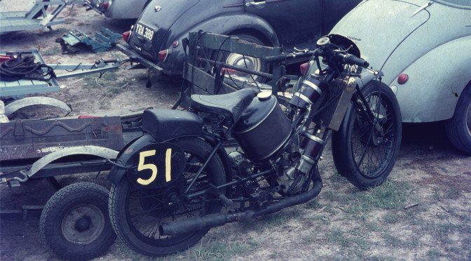
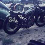
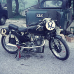
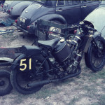
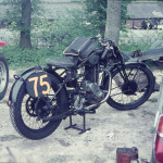
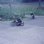
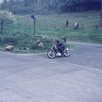
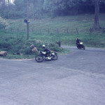
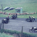
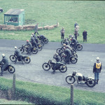
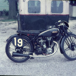
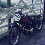
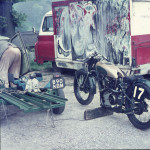
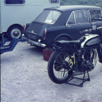
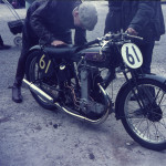
1960’s VMCC racing pictures from Cadwell
I was sent a box of 35mm slides recently, taken by the sender many years before at a VMCC Cadwell meeting. He thought it was the 1970’s, but I have an idea it’s the mid to late 1960’s because of the use of pudding basins and the car registrations. I might well be wrong. I have the use of a scanner and so have digitally converted them. They are a really interesting insight into the variety of machines being used back then. I’d like to identify the machines and the riders so if anyone can help with this or any other interesting information, please let me know.


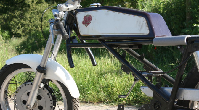
Dash to the North – the completion of the Silk Scott frame
I have a whiteboard in my workshop and it generally lists too many tasks that I am a reasonable amount of effort away from achieving. This last week however, I managed to get some significant ‘to do’s’ rubbed off the board.
The Silk Scott frame had been waiting at Alan Noakes’s workshop for me to come up with a plan for the final brazing solution. The lugs had been made to be brazed with a capillary fixing which really needed oxy-acetylene. I must admit that we hadn’t fixed the exact type of brazing material we were going to use and this was all part of the delay. I saw a clear weekend coming up and thought that this was my chance to push to get it finished. So the plan unfurled: first to get oxy/acetylene.
We’d had a plasma cutter at work that we’d bought from machine mart (please no comments). It was around £600 new and lasted a year and a day. The warranty department, were sympathetic but not quite to the point of being reasonable or useful, and I was told (after paying for the service) that it could be repaired for a sum of 500 and something pounds. I declined their kind offer. We’d only used it a handful of times to make register plates for woodburners and other bits and pieces. Normally around 3-4mm thick steel for a machine rated for 10mm. Anyway, since this incident I am resolved not to use them again and so was without any metal cutting equipment at work apart from grinders. So, I figured at £5 each per month for bottle hire, I could justify the oxy/acetylene. My Dad had an old portapak I could have and so I found myself at BOC sorting out an account last week.
I called Alan from the shop and enquired as to whether he’d got any prior arrangements for the weekend, and asked about rods. He didn’t and It didn’t seem that they had anything suitable, so I left with two bottles hoping that I could sort out the rest in the following few days.
I remembered a conversation with a man called Arthur Sosbe not long ago. Arthur, though now mostly retired, is a Leicester welder held in very high regard by my father. He is also a vintage motorcycle enthusiast and I believe used to race a velocette that used to lurk under a cloth in his workshop. I myself have known Arthur for many years and he has repaired many a Scott crankcase, as well as frost damaged barrels and many other fragile vintage parts.
Arthur had said that he’d naturally use silver solder, but when I quoted him a 0.010″ gap, he said that it was too wide and he suggested something else. I remembered this conversation and also that many lugged cycle frames used silver solder and I did a bit of research. A company called ‘Cupalloys’ came up as being suppliers of silver solder to model engineers, so I gave them a ring. I’d since confirmed the gap with Alan as being nearer 0.006″, which was within the capillary range for a 38% silver solder alloy which also apparently had the benefit of melting over a reasonably wide heat range, which gave scope to also create fillets.
I bought two packs of 5 rods, and at over £4 per rod, I hoped this was going to work.
So Friday came and later than I’d hoped, I packed the Moss crankcase destined for the Silk Scott into the van and I headed up country to Leicester to see Roger and to get the portapak and hoses/ regulators I needed to take up to Alan. I didn’t arrive until after 9pm but we gathered all the bits and pieces together, as well as a trophy I’d been awarded by the British Historic Racing club, the ‘Aotearoa Trophy’, gifted once to the club by a New Zealander. I believe it’s supposed to be the best performance of a 1930 and under bike. I won it last year also, and although it’s not that I actually won a race, it’s a beautiful shield with names going back many years.
We chatted, a lot, and eventually I got to bed around 1.30am.
So up and off to Alans, the offside front wheelbearing of my van starting to whine somewhat irritatingly.
I arrived at Alan’s somewhere after 10.30am and had thoughts that I might need to find a B & B for the night, as I didn’t know how fast the job would go with untested equipment and solder. I needn’t have worried because apart from Alan having to adapt some spacers to fit the crankcase, the whole process went very quickly. 
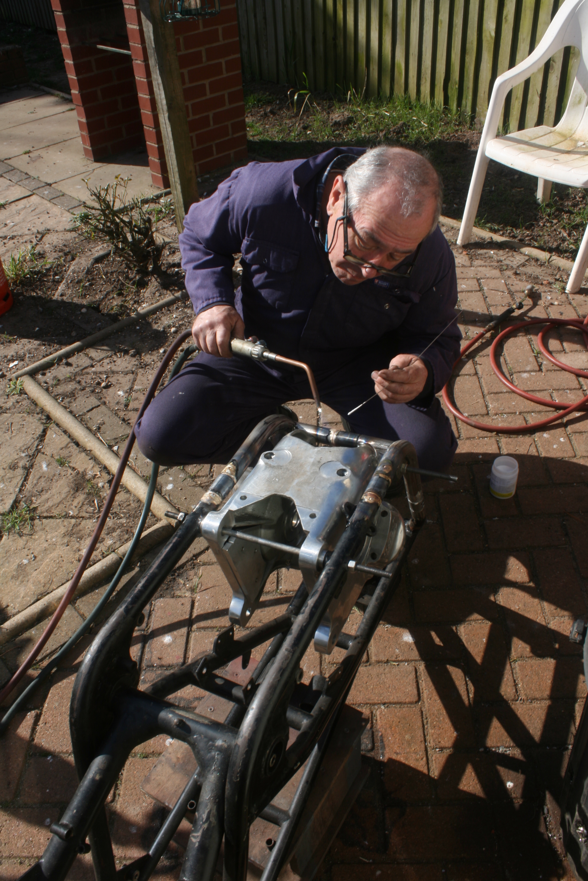
So onto the hot work and (making sure the detachable lugs all faced in the correct directions) using a propane torch and the oxy-acetylene, Alan soldered the new cradle assembly into the frame within a few short hours.


with a thanks and farewell to Alan, after he’d showed me some detailed bits he’d made for Scott TT replica forks, 
Colin Heaths racing barrels
I emailed Colin a couple of days ago to ask him whether he knew of anyone who had cut the bridges out of the transfer successfully and he sent me this. Thanks Colin.
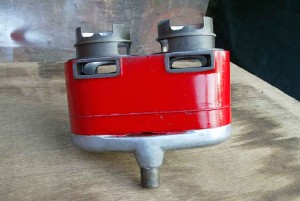
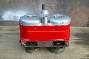

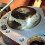
“Just a little more about the pictures. These are the barrels used by Martin Heath in that one glorious season when he won 12 events, including his first win. This was at Cadwell when he was left on the grid as the compression was so high the rear wheel just slid instead of turning the engine over, on the old downhill start by the timing/ commentary box. He managed to start it eventually by vaulting on from the greatest possible height and it fired up. The field were disappearing into Charlies by now, but he caught and passed them all to win. Proper Boys Own Paper stuff.
However, the point is that the barrel, as we had no other, was reclaimed by boring out the broken skirt from a damaged set and pressing in a flanged liner from the top. ( It sat in a machined recess). The machining had broken through into the jacket so good old Loctite sealed it all up and provided what I think is called a ‘wet liner’. We could not bring ourselves to put dividing bars back in the ports so made them elliptical as you see and relieved them to give the rings a softer time. You will also see that we needed to use a ‘detachable’ steel ring for the lower seal – and this located on a small step machined on the liner o/d.
Another simultaneous experiment was to make the liner full length down to the very bottom of the crankwell to see whether preventing any piston ‘rock’ would help. You can see the remains of this in the pics after it was later cut off. The rods had to be scalloped to clear the base of the liner, but we still use them to this day with no trouble.
The heads are a type you are familiar with and the drilled/tapped holes onder the dome on the exhaust side were so that we could use a head steady onto a frame cross tube. ( This was our super lightweight T45 frame, it was more of a frame steady than an engine steady. It was so light it sang like a tuning fork even after the engine was cut).”
I also sent him the pictures of my piston for his interest and to get his thoughts.
“As for the fuel pattern on the piston crown, by using a close profile high compression arrangement I expected that any ‘clean’ area on the side was trapped fuel ‘end gasses’ that got rudely pushed/ sucked out of the way before they had a chance to detonate.”
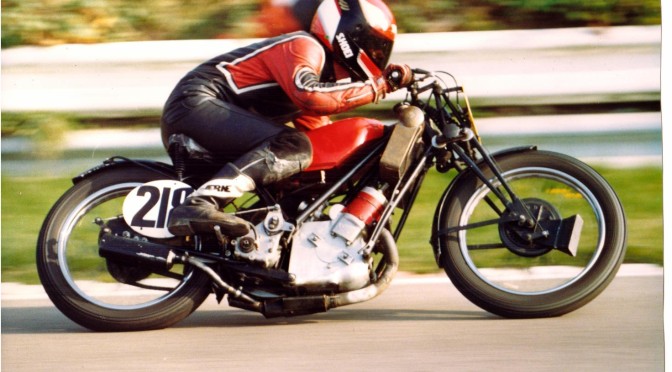
and of the photo of Martin:
I think it was taken at Mallory but expect Martin will correct me if necessary. Incidentally the silencer shown was our first effort after introduction of silencing regulations. This one is designed on the principle of ‘silencing by controlled leakage’ whereby multiple small outlets are provided under the crankcase all carefully pointed in different directions. From memory this set up has five intentional outlets including the official one. The theory is that one noise meter will have difficulty covering all directions at once. It worked well enough, for we would have been excluded on open pipes, and to my surprise the machine seemed, subjectively, to go just a little better than before.
March update: Super Squirrel carburation
The way I’d finished 2014 was with a rough set up of twin carbs on methanol. I’d modified the needles and the jets, but it was all way too rich (post meeting dyno results here) and a rush job really. The truth is, sometimes you have to push through to get something done, knowing that it might need work later. I decided that I would move away from methanol anyway after that last meeting and so it was a case of starting again.
I measured the port sizes last year and the inlet on each cylinder of the Super Squirrel is about 10.25cm². It’s actually less than standard, as we block the rear most inlet apertures up to allow us to put windows in our pistons to aid transfer flow. A Scott standard inlet gallery (cast into the skirt of the barrel) has a lot of small bridged ports which work fine in a standard road machine. In a racing bike, they are not able to flow enough gas quickly enough once the work has been done to enlarge the inlet tract in the crankcase which feeds them. This inlet tract is very restrictive in size and any serious attempts at performance usually involve some substantial work to open this up. The ‘floor’ of the tract rises up as it follows the radius of the central flywheel which is housed immediately beneath it. What we used to do was to reduce the diameter of the flywheel and weld up the bottom of the tract to enable it to be opened out. Of course such a measure means complete re-qualification of the bearing cups and barrel locations as the whole lot will be pulled in to the middle. Not a job for the faint hearted! You can of course improve performance by working on the tract without doing the floor, but it just depends how much performance you want to extract. My crankcase is one of Rogers improved castings with a better floor profile, thicker sections and far better material.
So the inlet was around 10.25cm², but I was using a single overbored Amal type 89, 
Since the Super Squirrel frame will not fit a larger single carb due to the frame tube being in the way, a split manifold seemed to be a good idea. Eddie Shermer made the one I have.

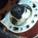
I figured that I would try and get close to the inlet gallery area with the carbs, and so settled on the idea of 2 x 1″ Amal 276 (or 76) with remote float(s) as this pairing give an area of 10.13cm². Although I don’t know what the relative flow characteristics would be between one carb or two of half the area, I guess that the flow rate might be less with two due to a greater proportion of drag from the inside of the greater surface area of carb venturi wall. However, the atomisation could be better. We’ll see. I actually had a 7/8″ Amal 276 and and 1″ 76 and was toying with the idea of getting the 276 bored out. I decide instead to keep an eye on ebay to see if something came up and thanks to someone on the Scott Owners Club forum who spotted one, I bought a singularly unhygienic 1″ Type 76 a couple of weeks ago. It had exactly the same smell as I remembered when my dad’s shed was visited by rats many years ago. I remembered they were so big that the cats used to sleep on high surfaces to avoid having to meet them. It required a lot of scrubbing to get to a point where I could inspect it…
So just the body and the jet block, well corroded in. An evening of gentle heat, wd40 and physical persuasion wrought success and now I am on the way to getting the carb setup back together.
While I was doing this, I remembered that I’d been meaning to remove the head to see if I could detect any patterns which might give some information as to how the bike was running. Initially this came out of a conversation with Ignition and bantam tuning expert, Rex Caunt at Cadwell Park last year and even though I was changing fuels I thought I’d have a look.
I was very interesting…
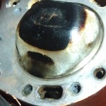


It could be that the clear sides of the crown indicate that I’ve achieved a functional ‘squish’ clearance preventing detonation (excellent article here). I’d really like to think that but I don’t (next day edit: I’m coming round, it might be a bit of this). It looks more like a tell tale that you wouldn’t normally see, but that my significantly over rich mixture is allowing me to see; the loss of unburnt mixture from the transfers straight owner the top corners of the piston into the exhaust. I might be wrong, but that’s my feeling.
It’s easy to see why it would happen, the transfer port is a bridged rectangular port which operates onto a deflector which is not rectangular, but is rounded at the top corners. The crankcase has stuffers cast in, which is a legacy really from the times where we weren’t running extractor exhausts. With stuffers and an extractor exhaust maybe it’s all a bit high speed into the cylinder and too much is being lost. Although I would expect to have some fresh gas returned to the cylinder prior to the closure of the exhaust port, this initial transfer gas would be short-cutting the scavenge cycle and so is not only unlikely to be returned but also not actually scavenging the cylinder of the remaining exhaust gases. What can I do if it is this? Well, Maybe some better shaping of the transfer bridge would reduce the tendency of the gas to bifurcate and disappear up and over the deflector. Maybe some mild shaping of the deflector could help. I had thought about removing the bridge but it does look like it’s too wide for the ring to cope.
I think it might be a case of planning a better cylinder and possibly looking at this for the Moss/Silk Scott racer too.
It’s all quite late now … I did spend about two hours scraping flat the exceedingly distorted flange on the new carb I bought but it’s still not done. Still, It’s all moving in the right direction.
