Category Archives: New posts

Beezumph 2014 report

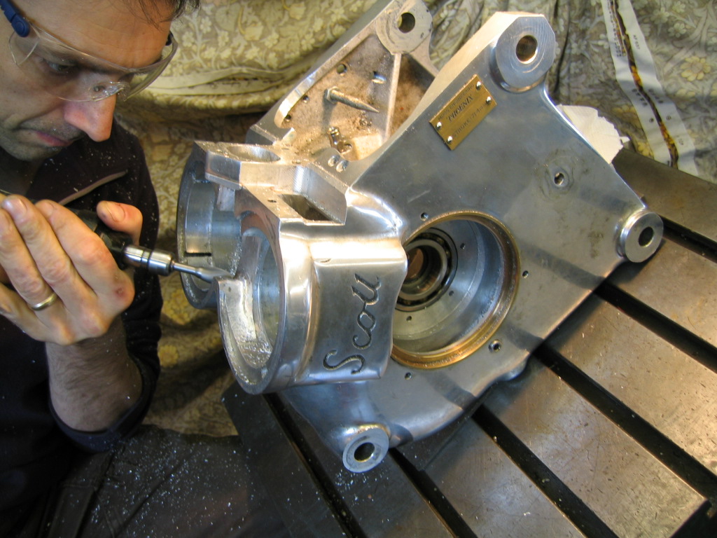
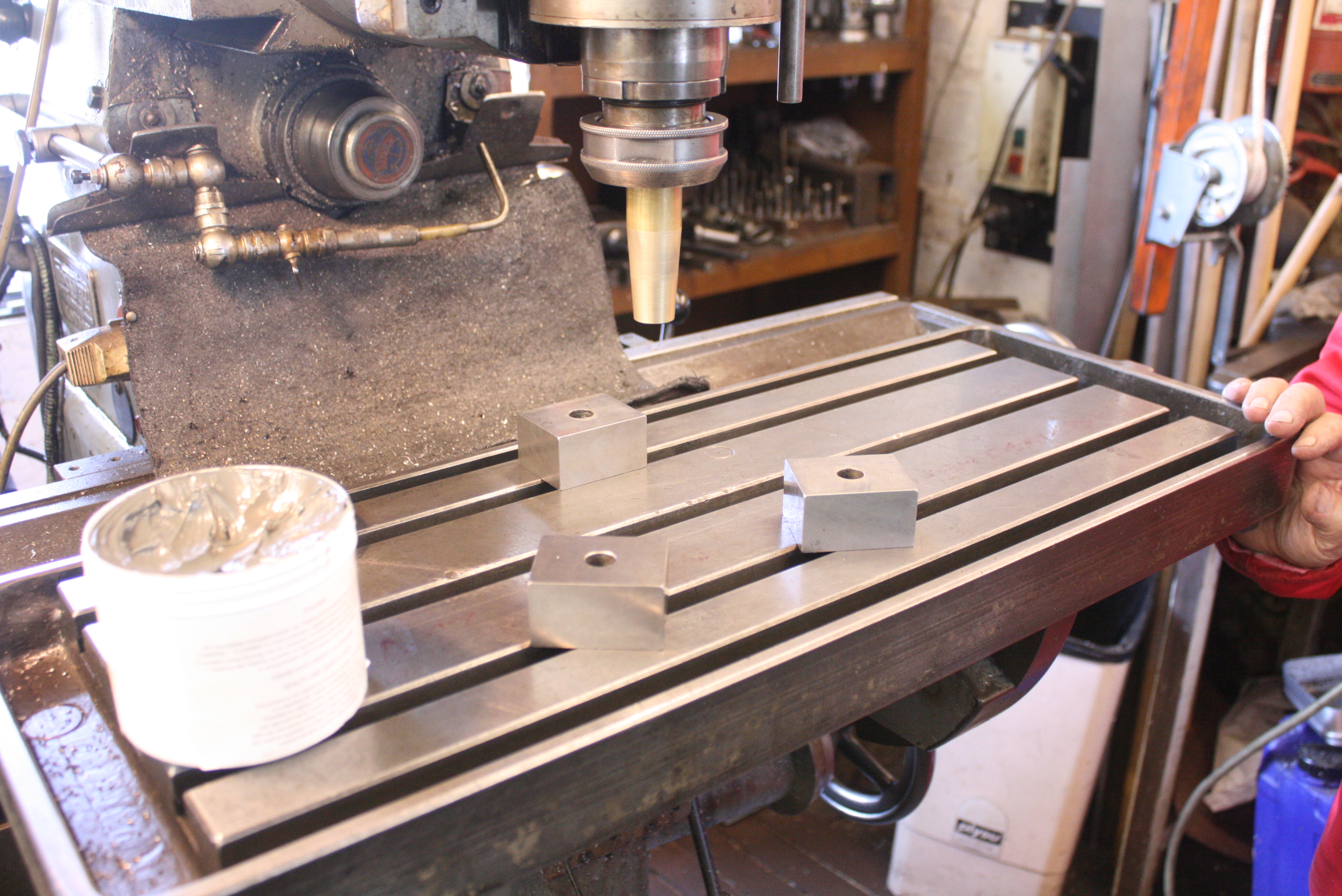
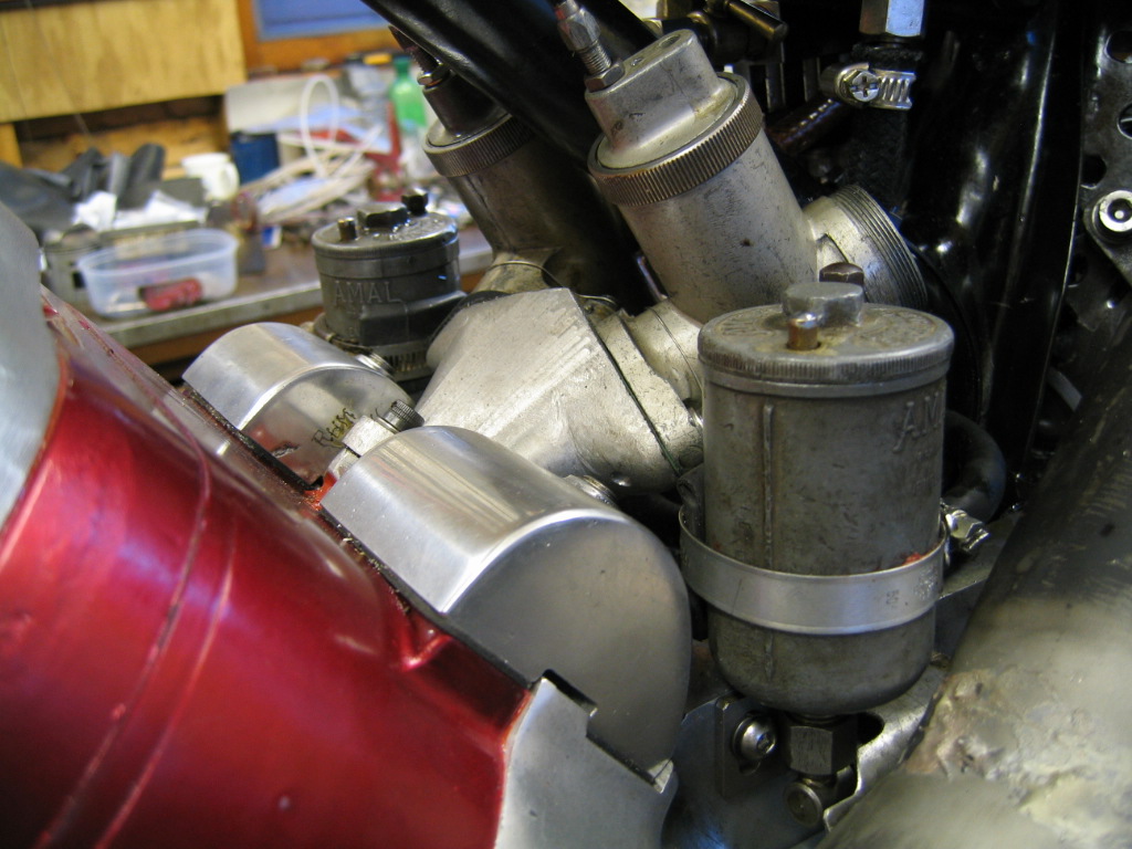
Well, I tried to get the twin carb manifold completed before Beezumph 23, on the 12th July but it was not to be and I was glad that I’d made the decision to leave intact the entire single carb assembly, fuel lines and all, just in case I needed to put it back. It was a close run thing and I actually still hadn’t finished the bike when it went in the back of the van but in fact retaining the single carburettor gave me the opportunity to assess the changes I’d made on the engine with more certainty as to what had affected what.

Just to re-cap, the Beezumph is not a race meeting but a track day organised by the vibrant Trident and Rocket 3 Owners club, many of whose members bring their machines out for this spirited social occasion. I first went in 2001, I think, and Roger a couple of years before that. I think it was his first return with the Scott to the track after some years of working hard to build his workshop and business. I believe that first time he attended he was awarded the ‘man of the meeting’ award by Doug Hele after having caused great amusement having repeatedly passed very much more modern bikes invariably by diving up the inside of them into corners.

I got up early as I still needed to finish a few details. Rear chain tension and corresponding alignment of the rear wheel needed to done, followed by the wiring of the rear brake torque arms and wheel nuts. A good check over and then put the kettle on for the morning coffee.

The fog that had descended on Cadwell park the previous evening lingered for a while in the morning lending it a brigadoon-esque feeling of a world apart which I’ve always felt Cadwell somehow symbolised anyway. You can be a hero just for one day at a race meeting, away from normal sensible life, normally in battling to fix things in adverse conditions. Two years running I worked ’til two in the morning at the last vintage Cadwell meeting, stripping and rebuilding a jammed Scott clutch (having three gears is hard on a clutch). I’ve ridden hundreds of miles to fetch a replacement component to fit overnight. We fixed a hole punched through Rogers crankcase by a fallen transfer cover bolt with epoxy and underpants so that Paul Dobbs could continue to race the same day. It’s still the same today.
So the fog delayed a little the start of proceedings but when it did finally lift, it revealed a beautiful day which was at times almost too hot in racing leathers.
In short it was perfect.

Beezumph has become a family favourite, and until very recently (Babies have arrived) there were regularly several of us making an event of it. As it was, three Scotts and their owners turned up to support us and it made a very fine line up in the paddock. Richard Rawson and his fine Silk Scott and friend on his very nice Birmingham Scott, and then Alan Noakes on his beautifully detailed, girder forked, Flying Squirrel.

2014-07-12 12.54.06
2014-07-12 12.57.17
2014-07-12 12.55.03
2014-07-12 12.55.58

I hadn’t mixed my fuel and so set to work with the ingredients. The engine had not appeared to have enjoyed a surplus of oil in the bores from my inspections after the previous season and so I’d decided to reduce the acetone percentage in the mix in case this was simply stripping the lubrication out. Acetone is one of the things that came up in my research when I was looking at running on methanol and my understanding is that it’s used to help combat pre-ignition in leaner fuel mixtures and possibly aid starting. I had decided on a 5% Castrol M, 10% acetone and 85% Methanol mix previously but this weekend I reduced that to 5% Acetone to see whether that made a difference.

Not having even run the engine since I started working on it at the end of last year, I was glad to have an offer to use someones starting rollers.

With the drippers set high feeding Castrol R through the non return valves direct to the main bearings she turned over for a few seconds before gradually starting to fire. A tell tale hanging of mist in front of the carb opening showed the effect of the extra inlet duration I had applied. I expected that that would only be present at lower revs, but we would see. When cold she always carburates poorly and there’s a significant lag on the throttle as if the cable has a length of elastic in it. After the engine warms up, she’s immediately responsive. Methanol simply runs so cold that when the engine is also cold the atomisation seems to be quite poor. That’s what I imagine anyway.

So up and down the pit road a couple of times and then out in our session.

The beezumph has different categories and they range from beginner (marshall led laps) follwed by classic, fast classic, open (any age of bike) and then expert classic. We go in expert or equivalent normally simply because you can get problems with people being unused to being passed around a corner in other classes. Last year in fact, Roger decided to go in the fast classic group thinking that class more appropriate. He was 72 and on a 1934 bike and so thought he’d give it a try. He found, as is often the case, that he was being passed down the straight by more modern, faster bikes which then proceeded to brake very early where a corner was approached. Thinking that they may be stopping to attend to natures call or maybe a sandwich, he would pass them. Some take seeing a pensioner riding a vintage girder forked bike up the inside of you at a ridiculous angle of lean with great humour and enthusiasm, but not all. Roger would invariably pass, undoubtedly at a significantly higher (if not warp) speed, until their desire to storm by on the straight was diminished by a growing sense of futility in the action. There-after some are merely crest fallen, whilst for the special few indignance steps in to protect a fragile self esteem..
One rider was so affected by this (whether through genuine fear or critically injured vanity it’s not known) that he complained and Roger was informed that if he wasn’t able to pass on the straights then he should not pass.
This year he returned to the self appointed experts class, where passing on corners is in fact expected.

The first session out, I was obviously quite sensitive to the engine’s character as much work had been done since last season. It seemed to me to have less torque low down and be therefore slightly less drivable out of the corners. However, the engine seemed to be be pulling longer through the revs and although the majority of bikes (750 Tridents and Rocket 3’s) were easily faster down the straight, it wasn’t the difference I would have thought. I thought I felt the engine tighten a couple of times (though I might have been over sensitive) so I took it relatively steady.

I raised the needle before going out the second time and was not to feel any hesitation again. I kept behind Roger for a couple of laps to get a comparison between his and mine and he thinks that I have about 2 or 3 mph on him on the straight. maybe 5. It’s doesn’t feel quicker than last year in the way it delivers power, but I think that actually I’ve made it breathe so much better that it’s simply getting more in at higher revs and therefore revving longer. Extra vibration has come with this, but we’re going to slug the bars with tungsten heavy metal to help here. Although my dyno tests last year are compromised by the fact that I’d blown a head gasket, I think the torque curve will be broadly representative and a comparison will show me what has actually happened. I look forward to getting it on there and will not change to the twin carbs before I’ve tested with the single. I’ll then swap the carbs before going back for another test. It’s going to be interesting.

So in the end, the bike was flying and little was able to get past and stay past. True, it’s a track day and not everyone is wanting to ‘ride it like they stole it’ though some are. It’s easy to walk away from a track day thinking that the bike is a rocket and that you are riding at the edge of human ability then go to a vintage racing meeting and get lost in the wake of serious riders on seriously developed machines. Saying that, mine is a seriously developed machine. By the time I get to the last vintage Cadwell it will have been my only race meeting this year. Family and work commitments coupled with a realistic budget have prevented me from attending more, but not in idle have we stayed away and I am hoping that when we do turn up to the last Cadwell at the end of September that we are able to move further toward the front of the field than we have before.

I’ve never won at Cadwell, and whilst I do all this for so many reasons beyond achieving a position in a race; this is what drives my desire to develop of course. To win, one day on my Scott Super Squirrel against good men on good bikes at full circuit Cadwell park. Of course it’s a folly, but what a grand folly!

June 2014 – a review

The rebuild of the Super squirrel racer is in its final phases.. and so it has to be as it’s entered for the Beezumph at Cadwell park on the 11th /12th July. I need to do a piece on the final assembly and some of the things I’ve experimented with.
I’ll default to the single carburettor that I know works if time really dissapears but I’d really like to try and get the twin carb set up finished and ready as it really might fly with a bit of extra gas coming in.

Ovally bored single carb used on the Super Squirrel since 1970.
One of the main reasons that Roger evolved from this single down-tube frame to the duplex frame on his bike is the ability to fit a bigger carb. He obviously felt it was holding the engine back. I thought I’d have a look at this further.

I’ve had a twin carb manifold for a few years which was made by Eddie Shermer. It splits either side of the single tube and gives you the advantage of standard two stud carb mounting rather than the unique Scott three bolt pattern. I have been intending to use the two Amal 289 carbs that I have previously used, albeit briefly, with this set-up. Although it seemed to go well at the time there was insufficient opportunity to really test its performance. That was with petrol, not methanol so a direct comparison is not possible. I have had a feeling that the 289’s will be too big though.

Twin carb manifold in position

A couple of years ago, when I first set the bike up on methanol I approached various people for advice. Roger Cramp of Velocette racing fame had built and developed two strokes to run on methanol and he kindly gave me the benefit of his experience about carburation. One of the things he said was that with methanol he’d found it very important to make sure that you had sufficient gas-speed over the emulsion tube to ensure that you had adequate atomisation, and he found that he’d reduced carb throat size to achieve better results. I imagine this principle applies to any fuel, but methanol is more reluctant than petrol to diffuse it seems. My single carburettor that sits behind the downtube is quite small and it works perfectly with good clean pick up throughout the range and it’s difficult to imagine that the pick up could be better. I don’t want to lose tractability so I thought I’d look at the relative areas.
Twin carb manifold made by Eddie Shermer

The inlet port on a single cylinder measures about 61mm x 16.8mm which gives around 10.5cm². I make no apology for change in units as I use what helps me visualise better! I’ve ignored the single bridge in this port, but reason that it will effectively make the port a little smaller.

The single carb I use at the moment is an Amal 289 bored out to about 32mm. This area is 8.04cm²
The 289’s I have are about 28mm bore and this is about 6.15cm². Two of these is 12.3cm²
A 1″ 276 is about 5.06cm². Two of these is 10.12cm². This would seem to be a better match.

It seems to me that I should try to at least have the carburettor inlet area quite closely matched to the actual inlet port area and that all my work on getting more gas in is a little pointless if I don’t increase the carburettor size. I think it will be very interesting to see what two of the 276’s will be like though although it’s going to be a push to get them and do the calculations for needle and jetting modifications before the Beezumph.

The engine is now together and primary chain and ‘magneto’ belt fitted and tensioned.
Securing the engine is a procedure on my Scott as it is fitted with ‘tie-bars’ which replace the lower frame rails. We tension these before the engine bolts are finally done up to pull everything together.
Also requiring a procedure is fitting the primary chain.

The Scott uses an ‘outrigger’ final drive sprocket which is secured through slots in it’s casting to the undertray. The undertray is an aluminum casting which bolts into a Scott frame and carries the gearbox and final drive as an assembly. The gearbox itself is secured using two long studs projecting from the bottom of the gearbox and passing through slots in the undertray to allow adjustment of the primary chain. Under acceleration the outrigger tends to get dragged rearwards along it’s slots, thus wearing the ‘high gear bush) in the gearbox putting bending moments on the output shaft and also encouraging the entire gearbox rearwards also. When this happens the primary chain tightens which puts pressure on the main bearings as well as buggering the chain, wearing the drive sprocket and wasting power.
One of the ways to avoid this is to cut out a little piece of metal to very closely sit in the slot of the outrigger to prevent it being dragged rearwards. Roger did this for years. Now we have snail cams fitted to the rear undertray mounting on the drive side to wedge against the back of the outrigger.
The other part of the gearbox bolting procedure is to make sure that after everything is locked in position, we make sure that the backlash in the adjuster for the gearbox position is taken out so that it also is playing a part in making sure that the gearbox is not pulled backwards. I then wire lock this adjuster nut in position. If this is not done, the gearbox will be pulled. The Scott 3 speed gearbox is a rugged device, but simply ‘doing the bolts up’ is not enough. These two procedures make sure that the gearbox stays where it should.

Holiday thoughts..

I’ve been away in France for a few days Holiday with my wife and our little girl and I thought I’d take a couple of motorbike magazines with me that I’ve never bought just to give me something to stick my nose in (as well as Jennings book on two stroke tuning, Tuning for Speed and a a great book about some of the lesser known stories from within the drama of the Tour de France). One of these was ‘Practical Sportsbikes’ which seems to be largely written by one man but has some really interesting bits and pieces in it. Mainly aimed at people who are interested in 70’s, 80’s and 90’s sportsbikes and still actually doing things to them to make them faster or better. One bit was concerned with the re-commissioning of a Suzuki RGV 250, which I’ve always had a soft spot for after having sat on one at the 1989 motorcycle show at the NEC. Anyway, they had decided to fit a programmable ignition unit which gave them the opportunity to pre-program advance curves and also to alter the timing using a plug in remote control. After realising that this wasn’t something that was that far beyond the realms of possibility, I wondered about using this on the Silk Scott racer, since no firm ignition set up has been defined as yet, beyond the use of the flywheel as part of the generator and ignition trigger.

Roger working on generator flywheel.

We're hoping it's all going to work out...
We’re hoping it’s all going to work out…
I wrote to the manufacturer mentioned in the piece at the beginning of the week outlining my interest and telling him the current situation.
I’ve had an email exchange this week which has been interesting. He admits that the benefits of an advance curve are likely to be greater in a higher revving engine, but he reckons that all engines benefit from it. It also gives speedy possibilities to set up in a dyno session, where the timing can be changed very quickly.
I’ve never had an advance curve on the system I run on the Super Squirrel and I’ve always thought it was fine. Without actually putting it on a dyno, It’s pretty difficult to know though.
He also says that the spark output is really good at low revs which means good starting… much better than a PVL system he said, which didn’t really crank out the voltage until the revs were higher. That would be nice.

The programmable ignition system is ‘zeeltronic’ (apparently popular according to this magazine article) and the website is here:

http://www.zeeltronic.com/page/home.php

They do systems that also control exhaust valves at different revs but the one he specified just does a couple of ignition curve programmes.

It certainly means that there wont be the fiddle of trying to make sure that the pickup assembly is adjustable. Apparently you set the pickup to sense the trigger just before the range you are going to be using and then the actual ignition firing points are decided by you in two programmable maps.

Also, since we won’t have any ignition or oil pump related gubbins hanging off the doors, I think that we should also do a set of reed doors for it such as Roger made for his brother’s bike back in the late 1960’s. Recently he’s had more castings made as they were used on the ‘phased transfer’ engine that Bob Collet has designed and built using Scott components as a basis.

Reed valve doors as designed, made and fitted to his brothers bike in the late 1960's
Reed valve doors as designed, made and fitted to his brothers bike in the late 1960’s
The more I think about it, the more I reckon that although reeds can be restrictive to flow in high revving two strokes, with the engine speeds that we are using there could well be a distinct advantage and with the high comp head and a resonant exhaust, it could be significant!

About time

I know a month is a lifetime in the world of blogging but the last month has been particularly tight in terms of time available to do anything other than work and so something had to give.
I have been working on the Scott Super Squirrel racer though, and after a trip to Leicestershire to visit my Father, Roger (and his workshop!), I’ve now at least got the bottom end of the engine together and working on the top end build.
I’ve been checking the piston to head clearances with a neat extendable rod he made years ago.

Extendable rod
Extendable rod

You pull it out to full length with the side clamping bolts nipped up against the spring washers, not to lock to assembly but to provide some resistance, and then you attach the piston with a dummy pin. Next barrel and head and then simply turn the engine over. Then lock the slide retaining screw up and remove. Then the centre to centre length of the rod can be compared against the length of your rod to give a reasonable indication of clearance available.
Before I re-assemble the rest of the engine, I’m taking the opportunity to start to mock up the twin carb manifold setup as it’s marginally easier to access everything without the barrel and head fitted.

I’ve had the manifold fitted before, back in about 2006, but unfortunately the engine I’d built back then suffered a rather catastrophic failure (unrelated) and by the time a new engine was built, it was put back in with the old single carb that the bike had always run with.

This weekends engine rebuild

After what must have been the longest Devon to Leicestershire trip I can remember doing, I arrived on Friday night with a view to getting the bottom end of the Scott Super Squirrel racer rebuilt by Sunday afternoon.

I knew that I was going to change the main bearings, as the ones I had were a bit notchy in the case. I also wanted to do some more gas flowing on the crankcase to allow me to use another inlet port that was blanked off by part of the crankcase as my calculations had shown that I was deficient in the inlet gas flow. I also wanted to check the static flywheel balance and the crank assembly end float and alignment.

The first thing I did was my porting as I knew I’d have to clean up the cases before replacing the main bearings.

Opening up the last inlet port.
It’s all so much easier with proper air tools! I’ve been spending hours with a riffler file to do stuff I could do with an air tool in less than half the time. Files are safer though! Easy to make a mistake with an air grinder.

Apart from a little de-burring here it is finished:

Just finished grinding the final inlet port access.
Scott cases ready and waiting for attention at Mossengineering
Roger working on a customers engine.

One of the first things we noticed when we looked carefully at the crankshaft assembly was there looked like there had been some movement on a crank taper. Wanting to err on the side of caution we set up a lap on his Thiel 158 jig borer to just make sure that the tapers were good and clean in the flywheel. A bit of gentle lapping and all was fine.

Lap for cleaning up minor surface damage in tapers.

Next, we checked the static flywheel balance before ‘knocking up’ the crankshaft/flywheel assembly for checking the distance between inner control faces on cranks. This, we compare to the bearing face to bearing face measurement of the crankcase to determine the end float as you cannot feel and measure it by simply moving the crank side to side when installed as I used ball races and not rollers as standard.

Static flywheel balance
Drilling flywheel for balancing

See here Roger’s magnificent Thiel 162 horizontal jig mill. We dug out the floor with a mini digger and filled it with at least 1 meter deep of concrete to create a sturdy foundation for this. Table rotates 360° and flips up to 90°, whilst the whole machining column can move in and out. The spindle then can be moved forward/back and up/down.

Thiel 162 Jig mill
Thiel 162 Jig mill

Tooling
Tooling

The Smart and Brown 1024 VSL lathe is a good place to put up the crank and flywheel assembly between centres (he sells these if anyone’s interested) IMG_4182We measure skip and run-out just to make sure there are no problems.
Checking the crank assembly for run-out

I made a new key, using slip gauges to determine the width. You have to be careful to check the height of the key as well as the length in case these prevent the flywheel tapers from safely locating in the flywheel.

Flywheel/ crank timing key. This is to time only and is not for driving purposes.

After all this, and before the assembly, the old bearing were removed and the cases heated to accept the new ones. The 22 tooth drive sprocket was deemed to be too worn and a replacement was bored out to suit the spigot and fitted.

measuring for the new drive sprocket

After that the new oil seals were fitted to the housing behind the main bearings and then the cranks finally installed and ‘knocked up’. The key doesn’t transmit load, it absolutely is not meant to… the taper has to do that. The crank tapers are driven in by tightening the centre bolt and then (with adequate provision to provide a dead stop on the other side) the centre of each crank is struck using an aluminium mallet, or large diameter drift alternately whilst continuing to tighten the centre bolt. There will come a point where the bolt cannot any longer be easily tightened and this is then considered done.

All in a very successful couple of days and a bottom end that should hopefully last for a while!

Scott Super Squirrel tuning continued- port calculations

It’s been a dispersed couple of weeks on the Scott front but I have been making progress. I’ve been reading the Jennings book on two stroke tuning from the early seventies. It’s quite well respected and has some fairly straightforward explanations of what modifications are likely to do what. The Scott is a bit unusual though and its extraordinary torque at low revs is something I would like to keep.
Let me say that everything from this point on is me trying to work something out, rather than prescribing a best practice!

It’s difficult to know who to listen to but I’ve used Jennings’ recommendations to establish the important points about the inlet, exhaust and transfer ports, those being the time that they are open and the area that is available for gas flow.
He doesn’t use the entire area, but actually has a method for calculating a mean area which is significantly smaller, but apparently more representative.
His assertion is that regardless of the size of a cylinder it will need a certain time/area to achieve optimum power at any given speed of crank rotation and I’ve created a spreadsheet to assist in calculating what’s happening. Doing the maths, combined with looking at the port timings of other engines, have given me some indications of where to go.

Ok.
This is a useful chart that was once published in Yowl:

Timing info

From having seen many Scott iron block castings, I can say that the port cores were seldom perfectly aligned. Certainly on my detachable head block the port apertures are at angles to each other and vertically misaligned slightly also between the two cylinders. The difference between cylinder timing durations is not insignificant: 4° on the transfer, 3.5° on the exhaust but only 1° on the inlet.

My own as yet standard timings (from one cylinder) started off as follows:

Exhaust: 159.5°
Inlet: 129°
Transfer: 134°

With those timings, I calculated using Jennings method that the combination of available exhaust port area and it’s time open would provide optimum power at 3500rpm, the transfer at 3250rpm and the inlet at about 3100rpm. Of these, the transfer and the exhaust figures are exactly standard, where-as the inlet differs for a couple of reasons.

1: As we have ported pistons to aid the gas flow from the crank chamber on the transfer phase, the rear part of the inlet gallery is blocked up on my engine (otherwise the port in the piston would communicate with the inlet gallery). This means that I have less actual inlet area available than standard. However, since the standard inlet gallery ports are quite small and each bridged, mine has the bridge removed between two and the port raised (as far as possible) to enable more area. My guess would be, that simply adding up the area without taking into account the effects of turbulence around the bridges at higher gas speeds is ignoring an important factor. Whether the gas speed ever gets high enough (given the amount of ports in the gallery) in a standard engine for this to be a truly limiting factor, I don’t know.
2: Our inlet timing is already extended from standard by the removal of about an 1/8″ skirt at the bottom of the piston. According to the tables available, this amounts to a difference of about 17° in total duration over the standard figure.

The standard port timings are really set up for a low engine speed, and the power and torque curves shown on dyno charts bear this out. Here are some charts to see this:

original Scott dyno test sheet

My Super squirrel racer, running methanol, tested on a dynojet rolling road dyno (albeit with RH blown head gasket) in October 2013.

Super Squirrel racer HP Dyno chart (Oct 13)
Super Squirrel racer torque curve (Oct 13)

Although the fact that the head gasket was blown means that the results themselves are not reliable, the curves are likely to be, and so I can at least see where (with the expansion chamber fitted) the torque and power is being made.

So you can see that the torque curve gives a good spread of consistent peak torque between 3200rpm and 4200rpm. You can also see that everything stops at 5000rpm, although I’m not sure I understand exactly what that shows. I’m assuming it is showing that the output drops off sharply and not just that the bike was only revved to 5000rpm during the test as you expect the curve to just terminate high if that were the case. This tailing off is definitely something to look at.

This torque curve does show that the output roughly corresponds with the Jennings based predictions. The expansion chamber will alter the results according to it’s own harmonics too, and in a perfect world I’d have run a straight pipe to try to remove that effect… but I only had an hour that time. I may do this in the future.

So, I should have a look at how this curve works within my gear ratios. It’s all a bit more important when you’ve only got three. I know it works really well at the moment, so I’m simply hoping that by not trying to do anything too extreme I shouldn’t have any problems.

I have set up the spreadsheet to show the % percentage of the optimum time area figure I am achieving for any given revs. This enables me to change a port duration figure, or a port width and instantly see its effect as a % of the optimum. Theoretically.
Alongside this, I also have some figures from A.Graham Bells book on two stroke tuning from the eighties which gave details of conclusions drawn from the known port timings for different engine configurations. By extrapolating the results to 5000 rpm, it seems 140° would be in sequence for the inlet, the exhaust would be around 165° and the transfer would seem to already be long at 134°.

So, how so these look on the Jennings spreadsheet?

As things are at the moment, the optimum theoretical rev/minute figure corresponding to my port timings (regardless of exhaust influence) is between 3100rpm and 3500rpm. With the above inlet port duration modification plus a little widening of ports, the figures say that I’ll be able to create the optimum time/area conditions for power at 4000rpm. That would be, around 135° for the inlet, 160°° for the exhaust and to leave the transfer alone.

I’ve got this week to finish the ports, I’ve ordered some new main bearings and next weekend I’ll be rebuilding the engine.

Roger’s Flying Squirrel racer – some pictures

Whilst I work out the port timing calcs, here’s a very early picture of Roger’s Flying Squirrel racer frame to illustrate his description in the comments to the post ‘The evolution of the Super Squirrel racer’

Top triangle was a design to remove the role of the standard frame's lower rails to retain rigidity.
Top triangle was a design to remove the role of the standard frame’s lower rails to retain rigidity.

The crankcase in this shot is, I believe the last standard Scott case that he ever used but fitted with the four bearing crank he made to help stem the tide of standard longstroke overhung crank induced engine carnage. Note the odd shape of the doors with the bolts in the middle. These are just blanking bolts; once removed a slide hammer can be attached to the doors to extract them as they obviously have to be a good fit to support the crank assembly.
The strength of the crank assembly was proven in quite extreme circumstances when there he started it at a meeting and it fired on one before hydraulic locking on the other cylinder, in which there had been a water leak. The contest of strengths was lost by the crankcase, which split across the main bearings. So much for sorting the crank problem.
Another interesting thing to note is the blind head block, which I believe was aluminium. This didn’t have any kind of higher compression inducing form work in the top to match the pistons, as his detachable heads do, but it would have been lighter than standard and running Silk pistons as we still do now.
just found some photos of the whole assembly:
Aluminium block and EN24T four bearing crank assembly. That's a titanium rod as well, in about 1977!
Aluminium block and EN24T four bearing crank assembly. That’s a titanium rod as well, in about 1977!

Also here’s a picture of him working machining a crankcase for Ted Parkin’s Scott. I believe this has extra large doors to take a set of special extra long stroke cranks.

Thicker sections, bigger port tracts, better material and designed to take replaceable main bearings with modern oil seals.

and here is Ted’s racer with new engine in place.

OLYMPUS DIGITAL CAMERA

Super Squirrel tuning for 2014

Although I’m unlikely to be able to afford to do anything like a full season this year, I’m pushing to try and get the Super Squirrel engine rebuilt to be as competitive as possible. It’s quite heartening to know that it went as well as it did as there had been little in the way of time spent on the detail of gas flow and port timings within the engine. Sometimes you have to stand back and re-evaluate why you are doing what you are and whether the original reasons still exist. I’ve done this and have some thoughts for ways to extract more power.

As it is, the port timings have been unchanged from standard, except for the inlet which has a slightly longer duration due to having relieved the skirt by about 1/8″. I didn’t change them because I didn’t want to lose the tractability and strong torque at low revs that the engine produces. I am still running a three speed box with ‘vintage close’ ratios and it’s important to have as much flexibility in the power band as possible. So, the idea was to increase the power and efficiency without narrowing the range too much.
The power of the engine seems to have been noticeably increased(though I lack proof of this) by using this new exhaust showing, i think, that it is effectively ramming unburnt gases back into the cylinder prior to the closure of the exhaust port. This has been a success which needs building on as I still think that there’s a significant amount of further power to be had by careful development.

I thought I’d start by looking at the obvious impediments to gas flow. I’ve been using Jennings book on two stroke tuning for guidance but essentially the idea is to have a gas flow which is not full of disruptive internal turbulance. The turbulences can be caused by changes in the surface of the ports, either things sticking up or the surface falling away (bumps or hollows). Also flow out of and into ports is facilitated by radii on edges. I’m applying this to all my ports and piston ports as a beginning, though minimally on the top edges of the ports where the timing will be affected. I’ve got a pair of Roger’s ‘high flow transfer ports’ which have no internal bridge and a non symmetrical shape, the idea being to send the transfer gas into the hump on the piston rather than over it. I always intended to spend time matching them exactly to the transfer ports on the crankcase and the block and two weeks ago I decided that the time was upon us.

I started with the crankcase and worked steadily on the left transfer aperture and found that when I’d absolutely matched the aperture to the cover, I’d increased the aperture from 904mm²(1.4″²) to 994mm² (1.54″²). That’s a 10% increase in area and the removal of edges over which eddies can form in the gas to restrict flow even further.

Transfer port work. 10% bigger on left before work commenced on right.

There was a bit of work to the covers themselves in matching to the transfer port openings on the block, but no work on the block on either the top or bottom edge , though a little at the sides to prevent the gas hitting the sides of the port. This gave me fractionally less area as it entered the ports. My understanding is that this is preferable as the gas speed is increased and the tendency to have internal turbulence affecting flow is less.
Once I’d dealt with these, I looked at the transfer ports themselves.
Whilst the engine was still together I’d noticed the height of the top of the skirt at bottom dead centre and found that it was around 1/16″ below the transfer ports both sides. To my mind this gave at least some opportunity to use some of this available space and at present I have elected to radius the bottom edge of the port to assist flow and also deepen the port in the middle adjacent to the bridge by that 1/16″ as well as radius the bridge on the transfer side.

before... (note blocked up inlets)
before… (note blocked up inlets)

Afterwards.
Afterwards.
I thought that there would be gas displacement when the flow hit the bridge and deepening the port there would give it somewhere to go.

The timings themselves are:

Transfer: 134°
Inlet: 129°
Exhaust: 159.5°

I have to be cautious about messing around with the port timings too much, as Scott barrels are no longer commonly (and cheaply) available should I completely mess it up. There is, however, a factor that has never really featured in Scott tuning before, that we now have got an expansion chamber exhaust which goes some way to (over) compensate for the effects of enforced silencing to 105 db. This means that the inlet gas, which was originally intended only to be subject to a pumped transfer is also possibly assisted by the expansion chamber extracting gases through the transfer, which would leave a negative pressure in the crank chamber. If this is taking place, then there is possibly also merit in extending the inlet duration further as there is possibility that more gas could be introduced without it spitting it back out. This also might be assisted by the use of the twin carb manifold and long inlet tracts contributing some inlet inertia to the situation.

previous engine with twin carb minifold fitted
Whether in fact the 289 carbs I have for this are too big to allow the gas speed and inertia required for this (and atomisation of the methanol) I don’t know. It’s be a suck it and see. I do have a rolling road dyno down the road and the smart money would be to run the single carb and then try the twin set-up and see the difference. Unfortunately my attempt to Dyno test at the end of last year to provide me with comparison figures didn’t go to plan as the head-gasket was blown from the beginning.

I need to do some port timing calcs (time/area) and continue the flow work to the crankcase and ports.

The Super Squirrel racer … where we are.

It’s not been the best couple of weeks for getting on with the Super Squirrel racer’s engine with both my wife and little girl both poorly and work being very busy indeed. A very good friend of mine also passed away, although this did rather contribute toward the quietness and patience required for gas flowing with riffler files.

So what is the plan?

A bit of history… In 2006 I finished re-building the old Super Squirrel racer and into it went a good Scott engine that I’d built with Moss crank. I sold this engine to fund another more radical engine build, and machined up my own head and heavily modified a Scott barrel to suit. I also welded up my own expansion chamber.
The crankcase I used had been a damaged case that we’d had welded, but had some evidence of cracks still remaining beyond the welding.

Anyway, I took it to it’s first BHR meeting at Mallory and it felt really strong for the first two laps, before it died. I didn’t really look at the engine until I’d pushed it back to the van, but when I did I realised that the damage was absolute to the crankcase. It was split in two and completely irreparable.

oh dear.
oh dear.

Upon reflection, the case wasn’t up to the job. I might have had some tiny amount of piston/ head contact too.. I know they were close as I’d had it before during testing and had worked to increase the clearance. The main bearing assembly was experimental and I think that also may have been a weakness. You live and learn and competition sometimes just brings the answers a bit quicker.

I had been working with my dad building the engines for a few years and I think this just happened just as I was going to move on to do a contract working to changeover a cylinder head line to a new head in the casting plant at Nissan in Sunderland. As I was not in a position to build another engine, my dad resolved to machine up one of his crankcase castings to at least provide a sturdy basis for a race engine. Into this he built the internals of the previous engine, and the new engine was badged ‘Phoenix’ in reference to it’s resurrection from the remains of its predecessor.

from the ashes...
from the ashes…

It was a fantastic thing to do for me.. I think because he felt quite sorry as I’d put so much work into the previous engine and also, that he felt that the far stronger crankcase casting was a far better place to start.

So I ran the engine for a couple of years, on petrol, and it kept going, but it wasn’t really competitive. It wasn’t really ‘tuned’, just solid and although I really enjoyed my bike, it wasn’t anything like as good fun to ride as my dad’s Flying Squirrel, which just had a sense of thrilling urgency that mine lacked utterly.

The catalyst for the major improvements that came was when my wife and I received a wonderful wedding present in 2011, in the shape of a new expansion pipe that my dad had made to fit by Gibsons exhausts in the South East.IMG_6831IMG_6828 My wife found this quite amusing. It was somewhat better looking than the one I’d welded up myself.. but did it work?

The first test came early in 2012 when we participated in the Prescott hill climb in aid of the blood bikes. With the same jetting as previously used with my old pipe I accelerated from the line hard and then pulled in the clutch quickly as it seized on the needle as I rolled it off.

We played around with it in the afternoon, changing plugs, altering the timing and jets but it just seemed to be running very hot. The next outing was at Lydden with the BHR club and we put in an extra head gasket to decrease the compression. It was still running a bit hot, but better… at least it finished a race. It really wasn’t quick enough though. I realised that I needed to make a decision.

It may be that the exhaust is not of the optimal shape and there may be a build up of heat because of this and not simply because it’s charging the cylinder so effectively… but we are not running a blank cheque development program (!) and so we needed to try and see if we could get it to work.

I figured I had three obvious choices. The first was to put my pipe back on. I did not want to do that .. It seemed such a retrograde step. The second was to work on getting the heat away. I’ve got a speedway radiator in the bike so a bigger one may well be much more effective. Also my dads bike has an aluminium cylinder barrel which also transfers the heat away from the exhasut port and cylinder head much more quickly than my iron block. Great. A new radiator would be about £1000 and a cylinder several hundred.

The third way was not popular with my dad.’Dope’ I said, that’s what I’m going to do, ‘run it on dope’.
The positives of methanol are that it really cools an engine and allows a far higher compression ration to be run than with regular petrol. Methanol also burns more slowly and that can make for a smoother and more progressive power delivery. On the negative side, it’s comparatively harder to get hold of, more dangerous to deal with and you need a much larger amount to run on. I’ve also experienced lubrication issues since I’ve used it, but it may be that some careful development may improve that. It also doesn’t give much warning in terms of plug colour if you are running lean. It tends to let you know by melting a hole in a piston apparently.

So it was that I invested in a barrel of your finest methanol and talked to a few people who had experience using it. By far the most useful contact was Roger Cramp, who used to race the highly developed Velocette that his son Ian now campaigns with the BHR. He had been involved in the building and development of an ariel leader that he had run on methanol as well as a Greeves. He confirmed the research I’d done about the necessary changes to ignition timing but also said to be aware that methanol was singularly averse to atomisation (at least when bucketing it in) and that high intake gas speed really helped. This encouraged me to stick with my smallish single carb to at least try out and see if it worked.

I decided on a huge 980 main jet and then measured the needle jet with a taper pin. I then put the carb together and drew lines on the needle at 1/4, 3/4 openings at the top of the needle jet and then worked out the dimensions of the needle at those points against the aperture open for air inlet. I ended up with a pretty severe taper on the needle, but it seemed to make sense.

I advanced the ignition by about 7°, closed the plugs right up and pushed. It fired up and it ran, albeit a little roughly, before I put it in the Van to took it to the last BHR meeting of 2012.

It was brilliant. The jetting seemed to work fine and there were no holes in the power delivery according to throttle position. The bike pulled and was so much fun. It felt totally different to my dads bike, but the torque and flexibility of mine suddenly made it feel like a completely different bike. It absolutely hammered the clutch though (as it does tend to with three gears) and I was up to 1am on the Saturday night stripping, releasing, filing plates and and rebuilding it.

2013 came and one of the first jobs I did was to rebuild the clutch with new GFS plates, laser cut. They were perfect really because I had to dremel each one to fit with abut 0.010″ clearance. The less clearance, the less hammering… My dad also had some pressure plate he’d had made out of solid, which didn’t flex like the original ones. IMG_3703These didn’t have the adjustable clutch actuation pins I normally used, which are a pain to set up. I made pins up instead from some silver steel and got them within 0.001″ of each other using a cordless drill as a chuck, a file, a dremel and some emery cloth.

We took it to a couple of track days, and then the last Cadwell park in 2013 and (with new 21″ racing tyres robbed off my dad’s poorly Flying Squirrel) managed a couple of second places and even a fastest lap. It was flying, although not in the league of Mike Farrel on his Rudge, who was really out on his own and un-catchable for us at least. You can lose a lot on the start as it’s difficult to get off the line with three gears when you’ve geared top for a long straight. Except for a CS1 Norton belonging to the famous Lewis family who’ve been campaigning Triumphs and the Norton for many years. I think everyone else runs four gears. It does make a difference.

I ended the weekend having blown three composite head gaskets and with the feeling that there was a bit too much piston slap noise, but apart from that it was the best racing weekend I’ve ever had at Cadwell. I also knew I needed to strip the engine and that I’d do some gas flowing whilst it was apart.

And that’s where we are!

Smart and Brown stripdown continues…

I’ve stripped the saddle off and have had the chance to see the good and the not so good.
The mechanism which shifts the main power travel feed to either the cross slide or the main saddle seems to be in really good condition and is a joy to behold.

Feed direction indicator on front of apron
In fact I think most things seem to be fine although I plan to diss-assemble, clean and lubricate everything even if there’s no actual damage.
IMAG0664
Both the top slide operating screws and nuts are very worn though as well as a few other bits and pieces.
Fortunately, I’ve made contact with somebody who has most of the bits I need, which is great.
The saddle is worn though and I imagine the top slides too, so there needs to be some precise measurements of wear and then some decisions made about refinishing work.
IMAG0658
This is a fairly big deal, but it can be sorted out.

I think when I’ve got the bits to repair it sorted out, then I’ll put a cover over her and leave her until the end of the season and just do some research on bed repair in the meantime. I don’t want to hurry this as it’s likely that I’ll have this lathe for a very long time. That’s my plan at least. Now I need to get back to the bikes. Really my priority has to be my Super squirrel engine, otherwise I’ll have nothing to ride this year. The Silk Scott racer’s frame is high on the agenda too.
Last week I picked up some 5mm MS plate to make some engine plates out of for the Norton model 18 and I have a plan for the Triumph engine…